
1. The Coverage Challenge: VHF/UHF vs. HF DX vs. NVIS
During emergencies, disasters, or tactical field deployments, operators encounter a physical barrier known as the “regional coverage gap”:
                       PROPAGATION COMPARISON

  1. VHF / UHF (Line of Sight / Terrestrial):
     [TX] ───► [Mountain Obstruction / Earth Curvature] ───X──► [RX (No Coverage)]

  2. Traditional HF / DX (Low Radiation Angle):
     [TX] ──/ (Low Angle 10°-30°) ──► [Ionosphere] ──────────────► [RX DX (> 1,000 km)]
          \____________________________________________/
                          ▲
                    SKIP ZONE (Dead Zone: 50 to 600 km)

  3. HF NVIS / "Cloud Warmer" (High Radiation Angle 60°-90°):
                       [ I O N O S P H E R E ]
                              ▲     │
                       (Vertical    │ (Shower / Mirror Effect)
                        Firing)     ▼
     [TX] ────────────────────────────────────────────────────────► [RX (Coverage 0 - 500 km)]
Obstructed by terrain, hills, or curvature. Reliant on repeaters which frequently fail due to power cuts during disasters.
Low takeoff angle (10°–25°) for intercontinental links. Creates a Skip Zone of 50 to 600 km with zero coverage.
Near-vertical takeoff (70°–90°) reflected by the F2 layer as a uniform RF shower over a 0 to 500 km radius without dead zones.
2. Frequency Windows and Operating Bands
NVIS propagation cannot be used on arbitrary frequencies; it is strictly dictated by the Critical Frequency of the F2 Layer (foF2). If transmission frequency exceeds foF2, the wave punches through the ionosphere into outer space.
                  BEHAVIOR RELATIVE TO CRITICAL FREQUENCY

         Frequency > foF2                        Frequency < foF2
      (Lost in outer space)                     (Total NVIS Reflection)
            ↑   ↑   ↑                                 ↑       ↓
       ═════╪═══╪═══╪═════ F2 Layer              ═════╪═══════╪═════ F2 Layer
            │   │   │                                  \     /
            │   │   │                                   \   /
           [Transmitter]                              [Transmitter]
Optimal Bands for NVIS:
| BAND | FREQUENCY RANGE | NVIS OPERATIONAL USE | IONOSPHERIC BEHAVIOR |
|---|---|---|---|
| 80 Meters | 3.500 – 4.000 MHz | Night / Early Morning | Indispensable when the ionosphere cools down and foF2 drops (typically between 2 and 4 MHz). |
| 60 Metros | 5.330 – 5.405 MHz | Transition (Dawn / Dusk) | Ideal bridge band when 40m has not opened yet and 80m suffers elevated static noise. |
| 40 Meters | 7.000 – 7.300 MHz | Daytime (Full Sun) | The primary daytime NVIS band. Solar radiation increases ionization, elevating foF2 beyond 7–9 MHz. |
| 20 Meters + | > 14.000 MHz | Not applicable for NVIS | Except during extreme solar events, high-angle waves escape to space; reserved for DX only. |
3. Principles of the ‘Cloud Warmer’ Antenna
An NVIS antenna is not just any wire dipole; it is intentionally engineered to maximize zenith (90°) radiation while attenuating low-horizon radiation:
- Low Elevation Above Ground (h < 0.2λ): Placing the dipole at a small fraction of a wavelength from the ground (between 0.1λ and 0.15λ) causes the ground to act as a natural reflector, directing the primary lobe straight upward.
- Tuned Passive Reflector: Real ground often has imperfect conductivity (dry dirt, sand, or rock dissipate RF). To correct this and gain 3 to 6 dB of additional zenith gain, a parallel reflector wire is placed underneath the driven element.
- Reception Impact: By nulling low-angle takeoff, the antenna drastically cuts atmospheric noise (QRN), distant static discharges, and interfering DX stations on the same channel, yielding exceptional signal-to-noise ratios (local signal reports of 9+20 dB to 9+40 dB).
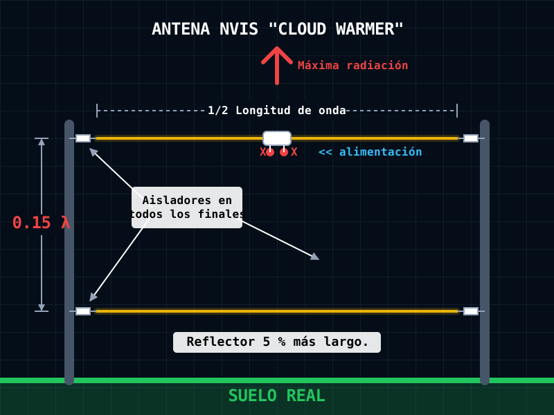
4. Design Calculation and Construction Guidelines (40-Meter Example)
142.65 / F(MHz)Dipole × 1.05 (+5%)45 / F(MHz)🔬 Practical Example: 40m Emergency Center Frequency (F = 7.150 MHz)
- Driven Element: 142.65 / 7.150 = 19.95 m (two legs of 9.97 m each).
- Passive Reflector: 19.95 m × 1.05 = 20.95 m (single continuous uncut wire).
- Optimal Vertical Spacing: 45 / 7.150 = 6.29 m height separation.
Field Configurations:
- Central Mast / Inverted V: Dipole apex at 6.5 m height and tips at ~2.5 m. The reflector wire runs directly underneath on or near ground level.
- Ground-Level Reflector: In rapid tactical deployments where intermediate rigging is impractical, laying the 20.95 m reflector wire directly along the terrain under the dipole significantly enhances the reflection plane.
5. Tactical Value in Emergency Operations (EMCOMM)
Direct point-to-point links between hospitals, emergency shelters, and command posts without repeater dependency.
Vertical skywaves descend overhead, bypassing deep canyons, cordilleras, and dense rainforest canopy.
A lightweight telescopic mast or tree limbs allow a fully functional NVIS base in under 15 minutes.
With zero multi-hop skip losses, modest power (20–50W SSB or 5–10W digital) delivers solid, fade-free reception.